HOW TO MAKE [ALMOST] ANYTHING_MAS.863
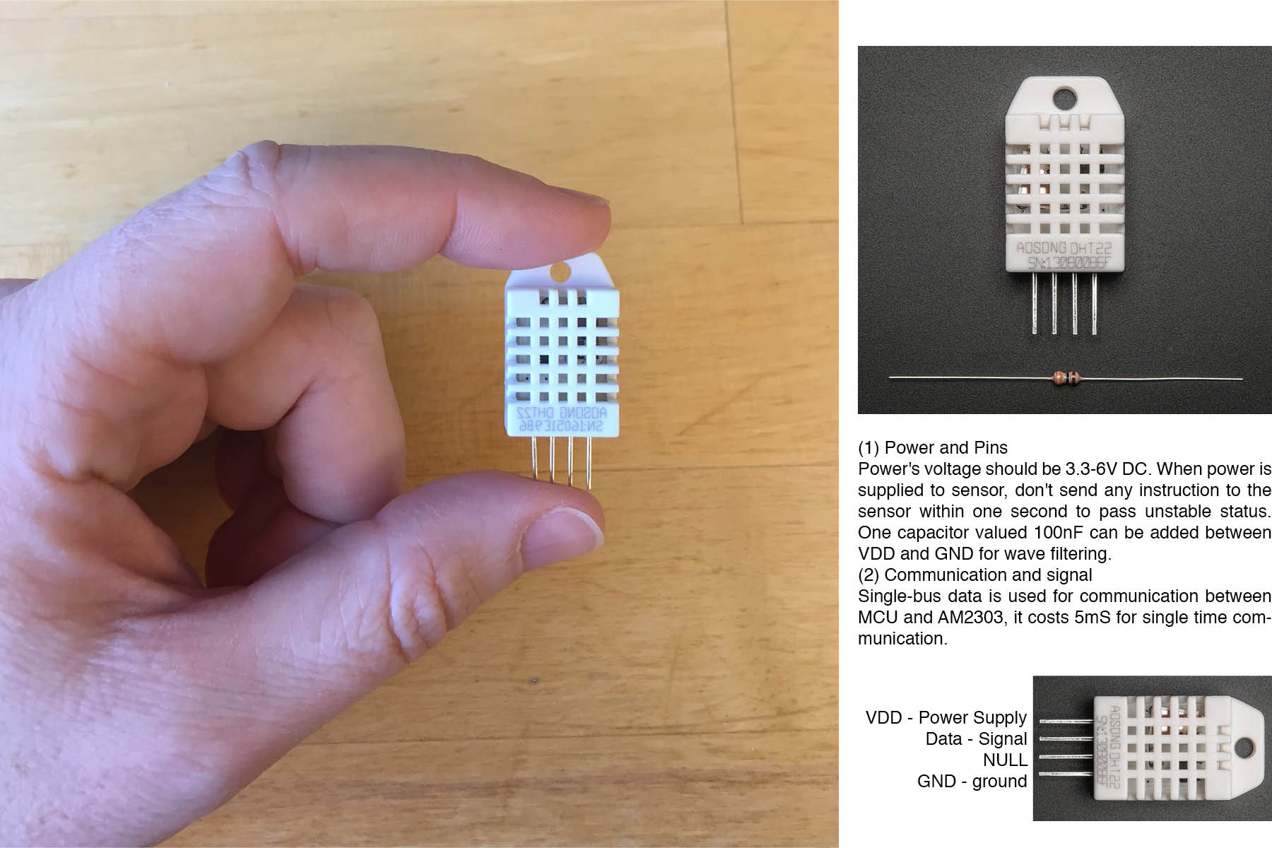
Input - Temperature and Humidity
Some of this is duplicate information from Week 08 - Input Devices, so if you're looking for more detailed information about that process, please take a visit to that page.
This weeks assignment was to measure something: add a sensor to a microcontroller board that you have designed and read it.
The data sheet for this sensor was much more straightforward than the ATtiny data sheet... except for all the Japanese.
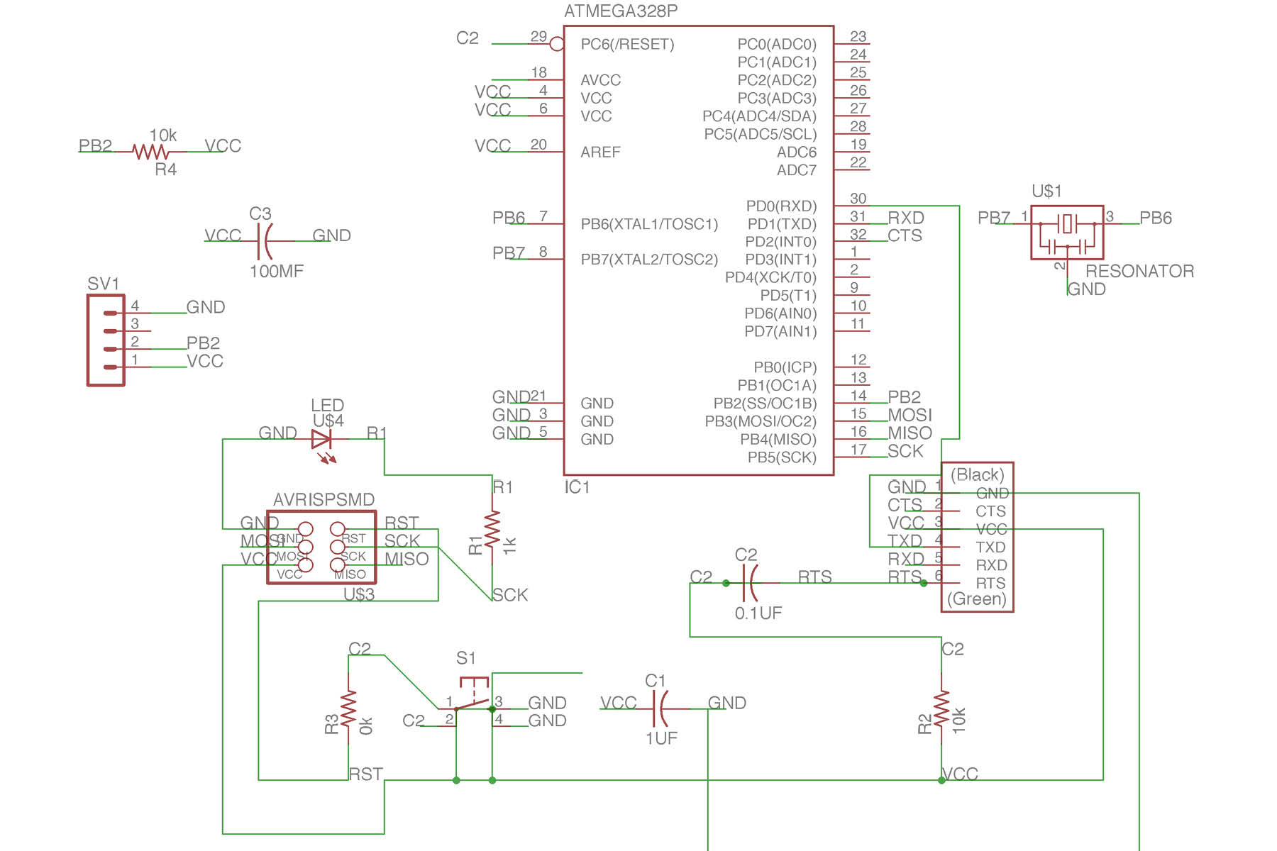
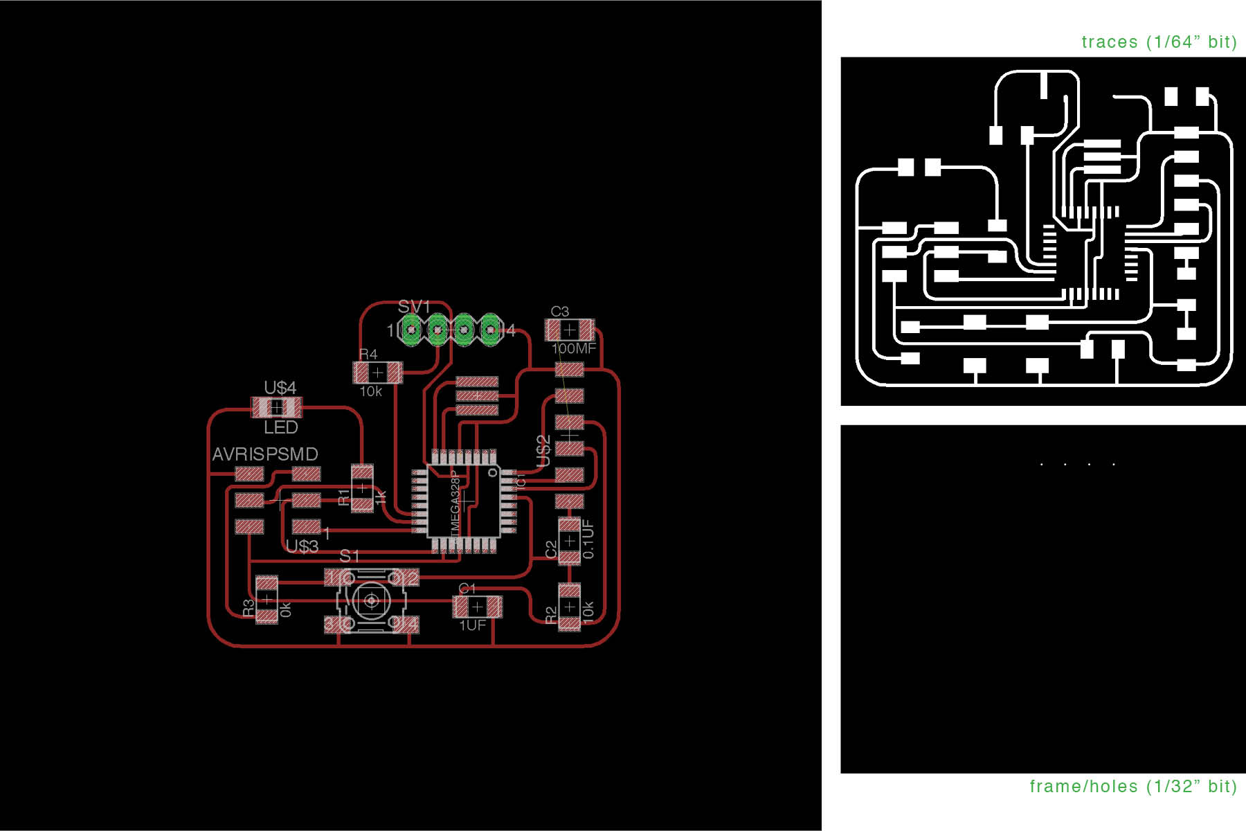
Here's the schematic from Eagle.
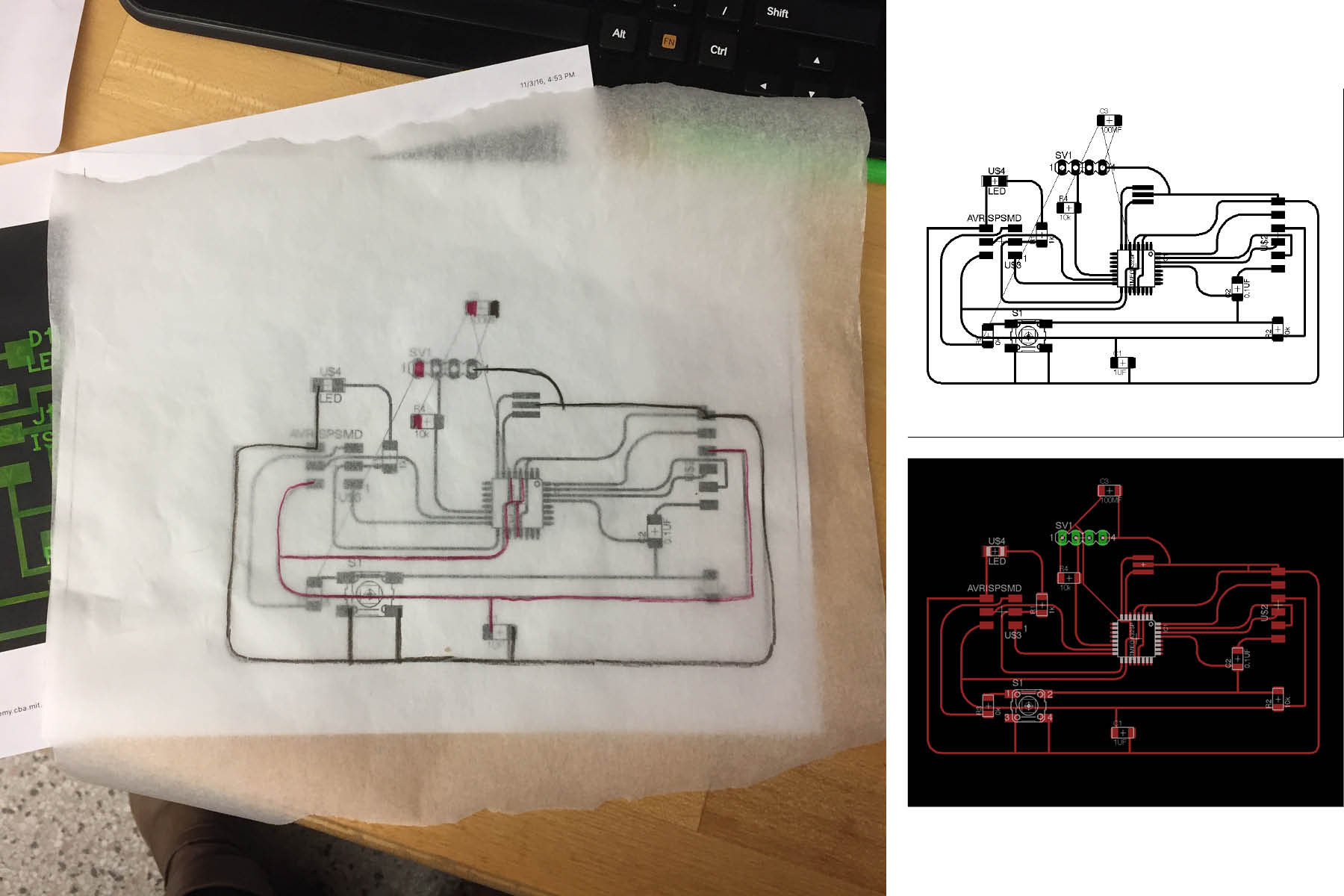
This is the most complex board I've ever designed, and I had a hard time getting all the traces in order without overlapping eachother. I did try the autorouter this time for some ideas but ended up figuring it by hand using trace paper and colored pencils (trying to keep the VCC and GND straight).
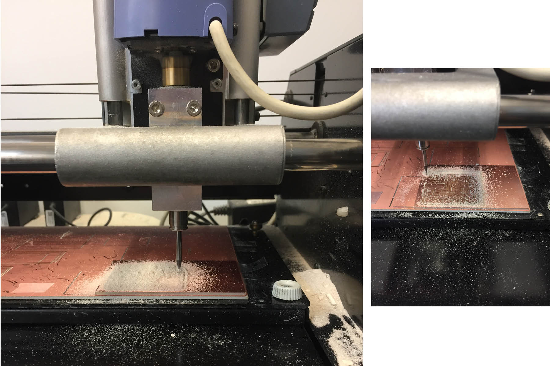
Milling feels pretty easy at this point, so I'm happy about that. If only I could stop making dumb mistakes with my files or the setup. This board took longer to cut than any of my other boards (~30 minutes for traces).
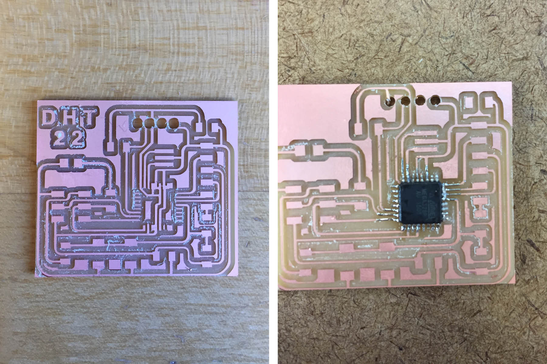
The image on the left was my first attempt. Some of the traces were too fat and there was a lot of overlap. Also, the holes that I drilled for the DHT22 were way too big.
The image on the right was my second attempt. The holes were still too big but I decided to go with it. Lesson learned here: don't solder while hungry. I had a really hard time attaching the chip - I couldn't get it lined up with the copper pads, and once I finally did, I couldn't control the solder. I tried to create a big glob and use braid to clean it up as Neil recommends, but I couldn't get the solder out from between the pins, so everything was connected. I found a bit of success in scraping the solder away with a knife and some tweezers (since the soldering iron point wasn't sharp enough) but after being a little too foreceful, I broke one of the pins and ripped the copper off the board, so it was all over after that point.
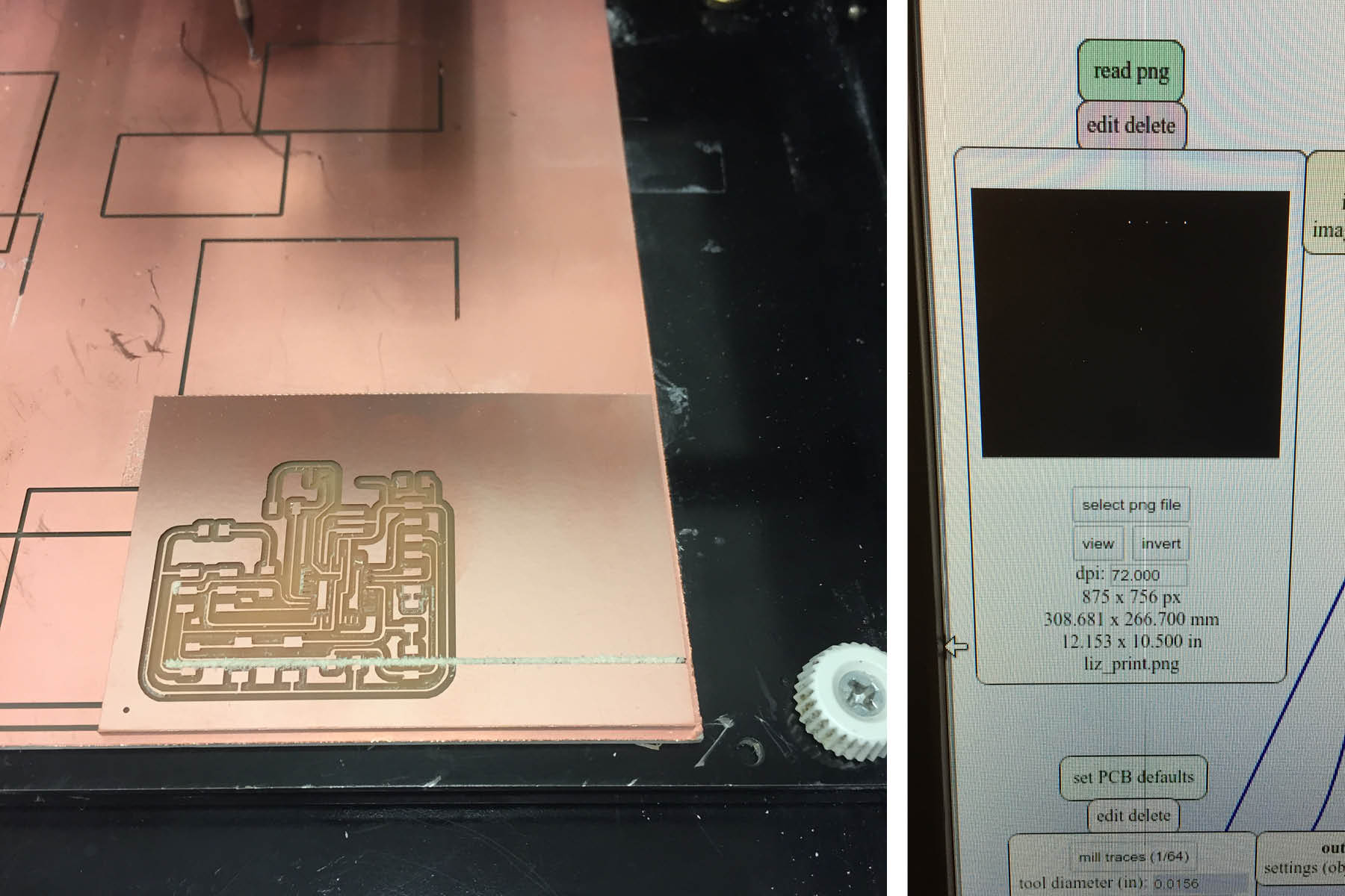
dumb dumb dumb. After making it through the traces in 30 minutes, I sent the frame .png to the mill without changing it to 500 dpi - it was on the default 72 dpi. It cut right across my traces. Bummer.
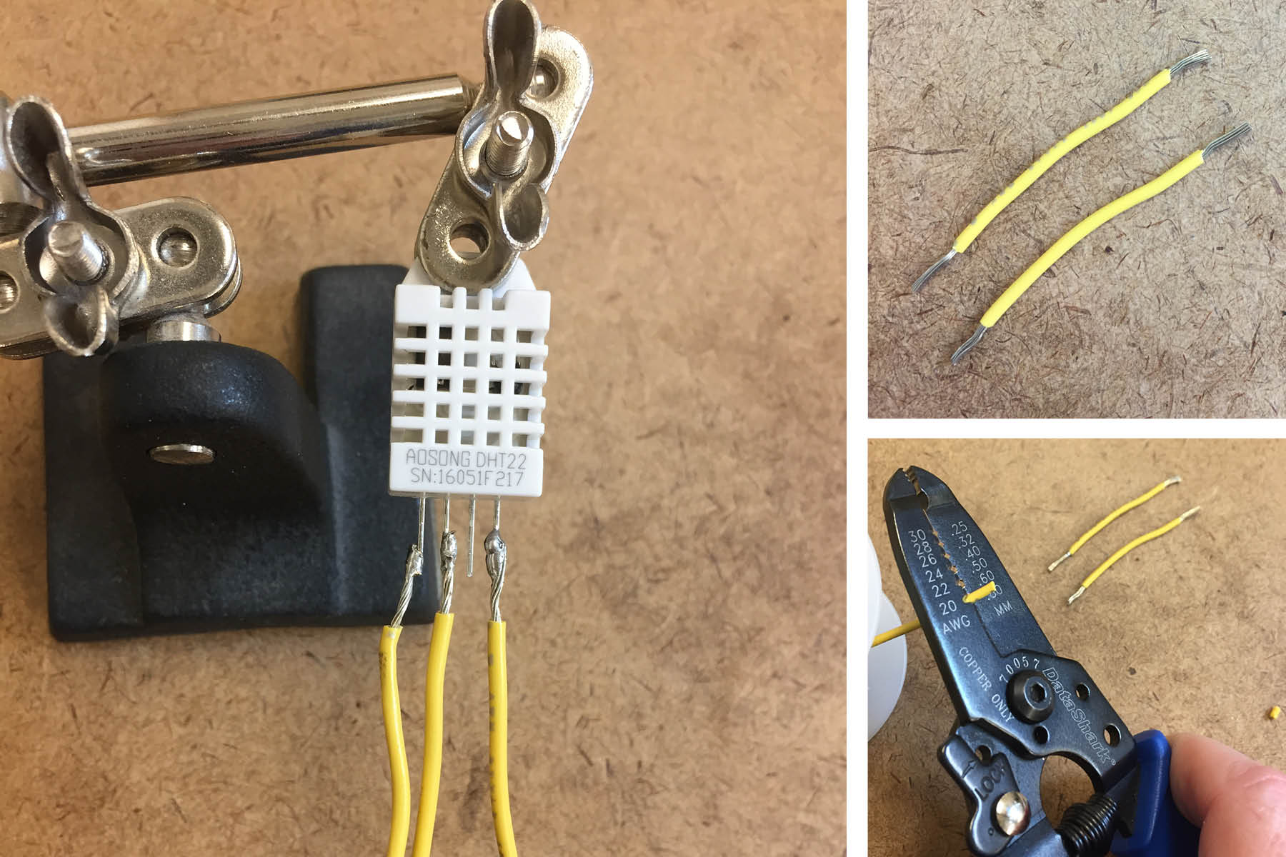
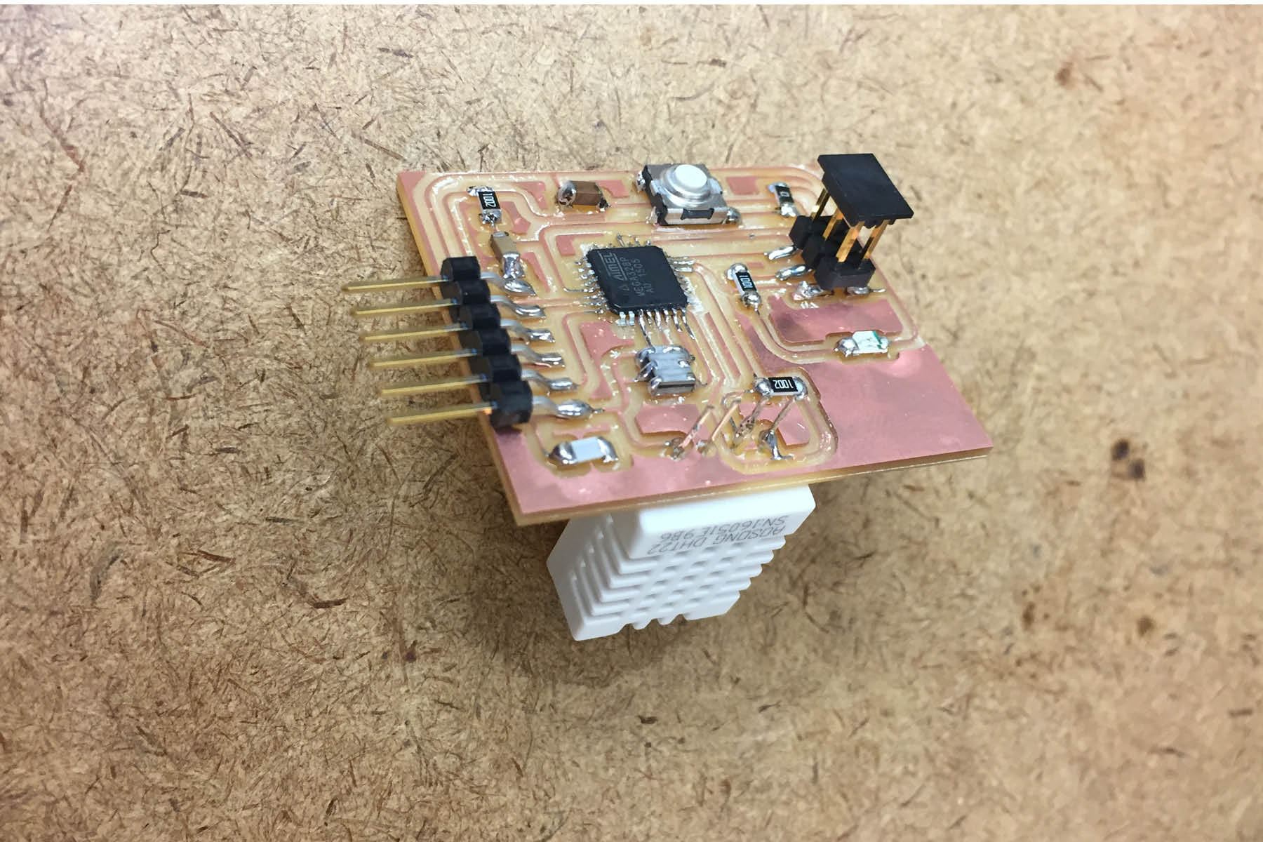
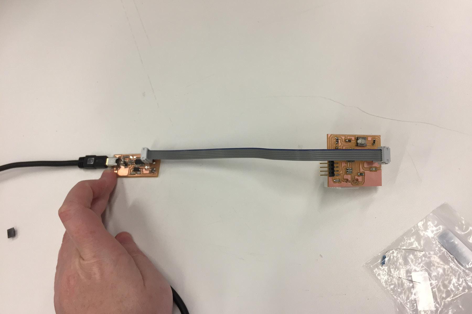
These temperature/humidity sensors were a little expensive, so I was sensitive about fully anchoring it to the board when I wasn't sure that it would work, given all the milling issues I was having. One of the TA's suggested that I connect it with wires, so that it's easy to desolder and I don't need to trim the pins. In the end, I decided that this was ugly and I wasn't entirely sure how to connect it to the board, so I opted to solder it directly to the board upside down (but without trimming the pins)
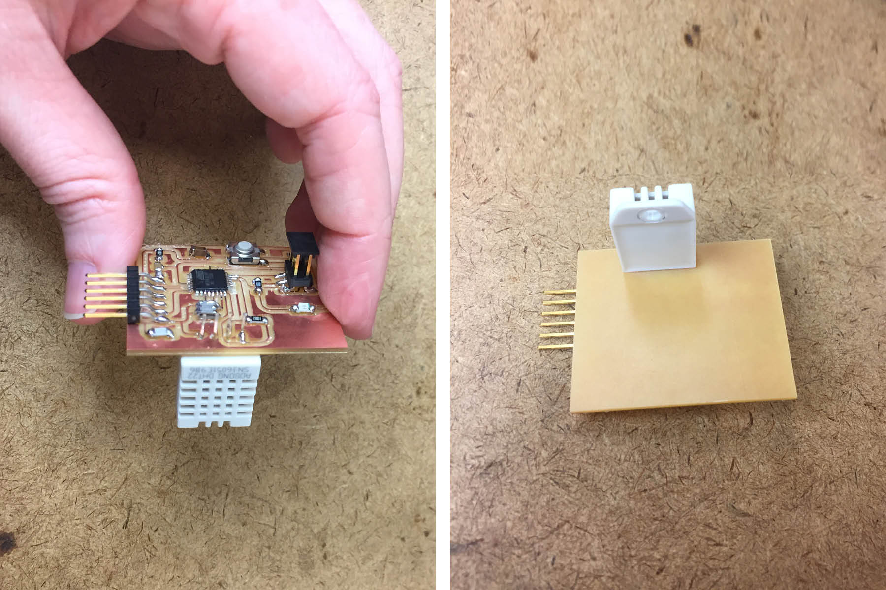
Soldering this on was easier than I thought. Now I need to figure out how I'm going to use it in my environment box before I decide if I'm going to use the wires or not. As a side note, I had to rotate the sensor in order to keep it with the correct paths.
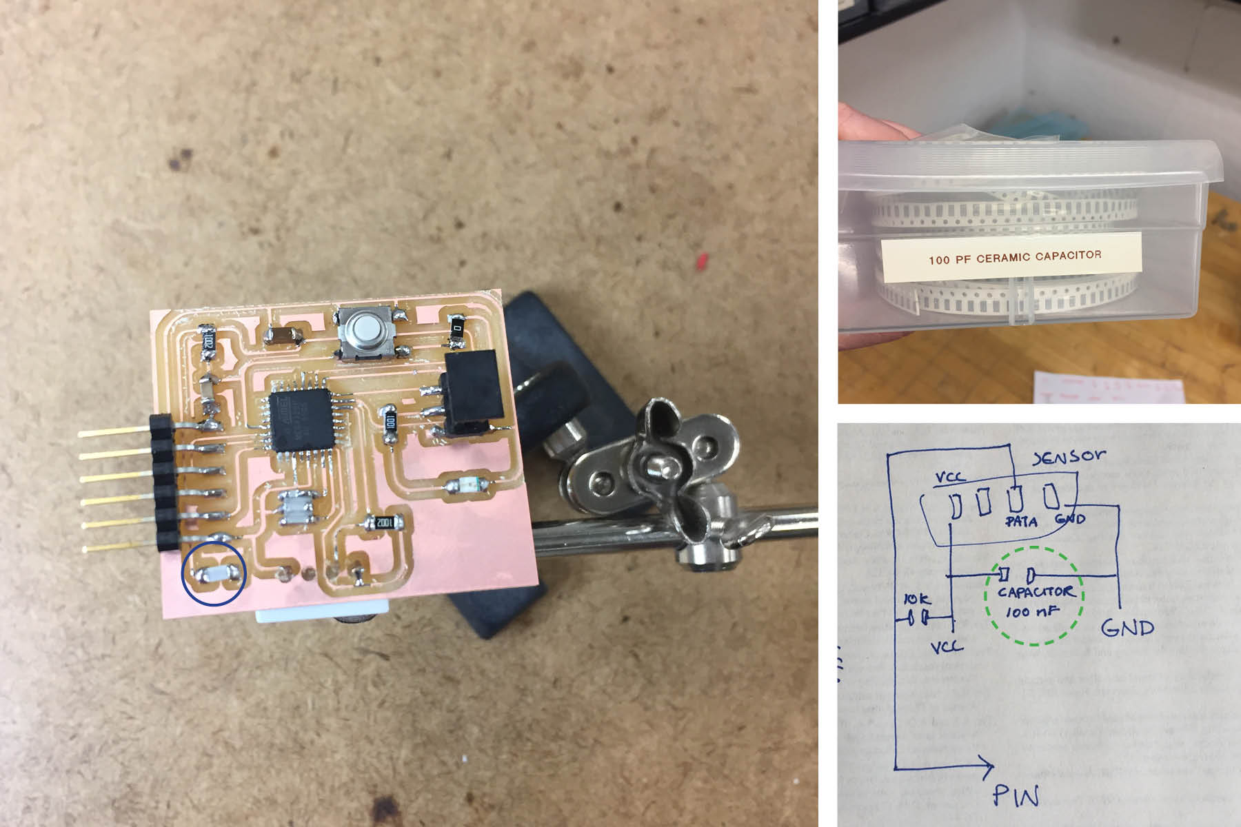
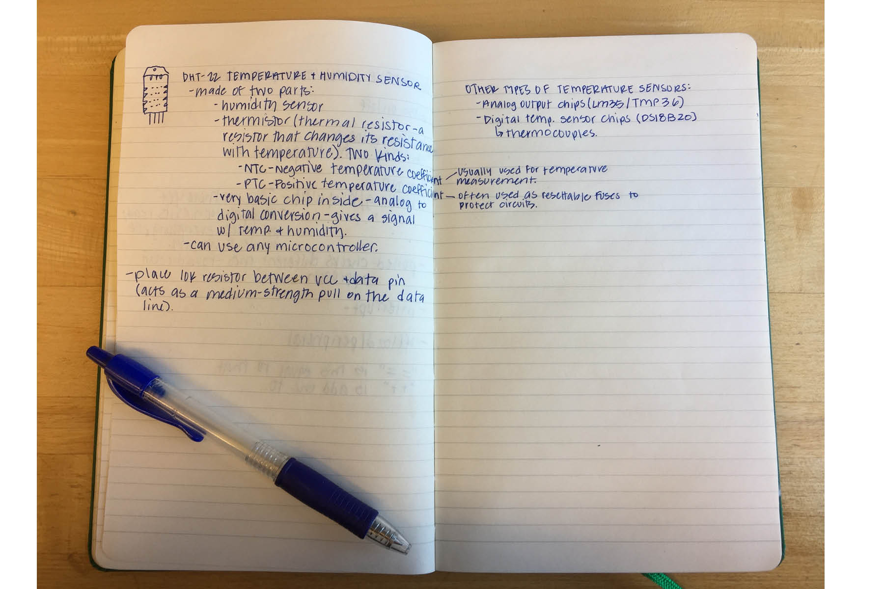
When meeting with the TA, she drew this little sketch for me so I could add it to Neil's Hello.Arduino board from the embedded programming week. I need to follow up on the "100 MF capacitor". I assumed it was 100 UF, but I could only find 100 PF. I'm not really sure what any of it really means, so I don't know if I've installed the correct piece.
And here's the final board.
Dan Chen Lab: "tips for getting Arduino IDE working on your own board" was a helpful tutorial.
Plugged into the programmer here - make sure to have the wire facing in the right direction. This one is right for my board. Steps to program the board (after you do this, you can get rid of the programmer):
Slect Board. Tools > board > DIY Atmega328
Slect Processor. Tools > processor > 328P
Set Speed (important to get right). Processor speed > 20 mhz
Use bootloader. Tools > programmer > USB tiny ISP. (Lower level firmware gets microcontroller in a state so it nolonger needs the programmer)
Test it. I have an LED installed on my board so I was able to use one of the aruino example files to check if it blinks.
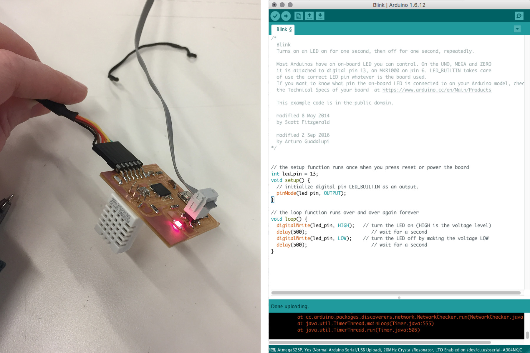
AND IT BLINKS! this is good. I had to change the pin to 13 - explained below.
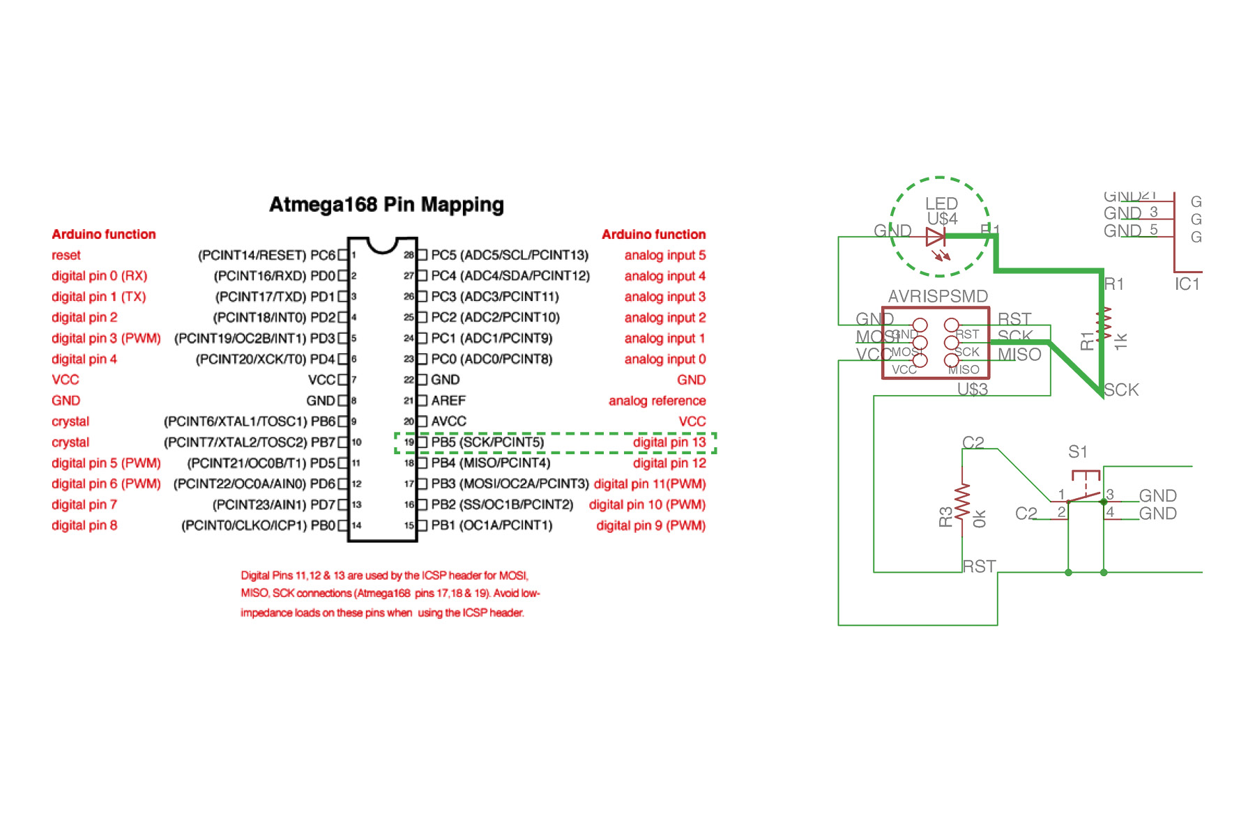
I found this image by google searching "arduino 328 P mapping". Arduino uses different pin numbers so you have to translate it. On the image on the right (my schematic), you can see that the LED is wired to the PB5 SCK pin. Looking at the image on the left, you can see that this is actually pin 13 on ardunio, so that's the pin you use. You can see in the code above that I change the pin number to 13.
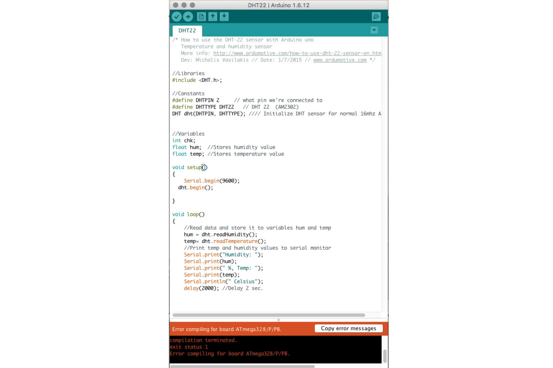
So I copied some example code from adafruit that people have made for this sensor. I sent it to the board... and I have no idea if it's receiving or not. Where does the data go??